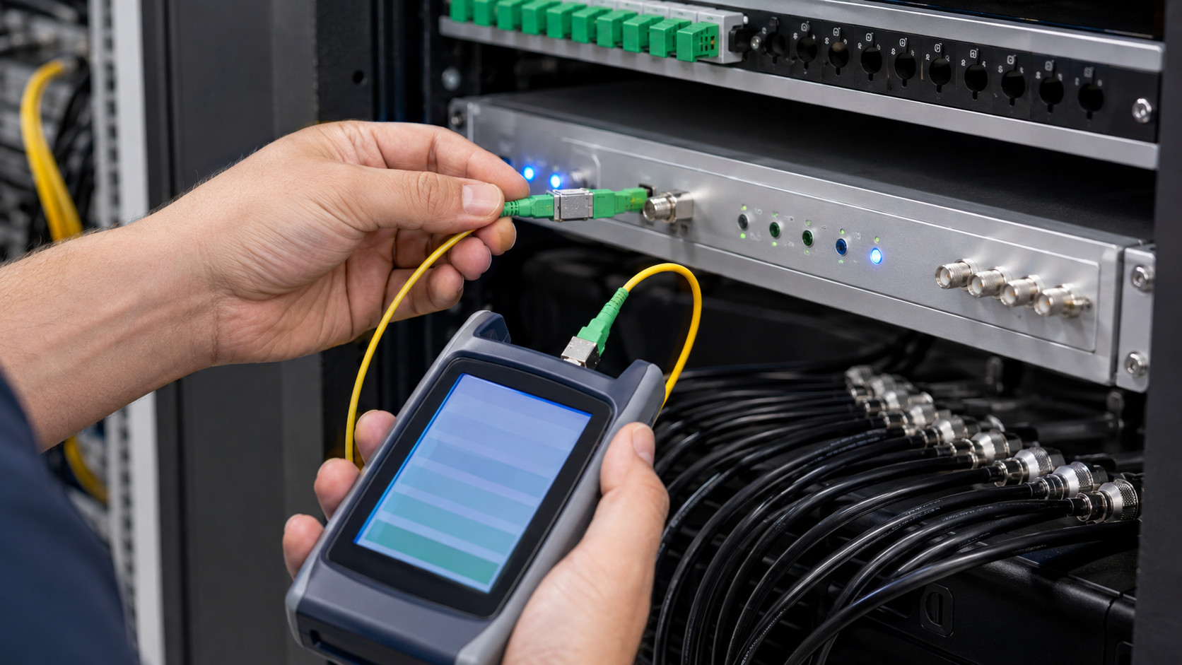
An optical attenuator is needed when the light reaching a CATV RF over Fiber receiver is above its recommended operating range. It is particularly common in short links, high-power 1550 nm systems, amplified networks, and installations with minimal passive loss. Reliable attenuation begins with accurate optical measurements and the manufacturer’s transmitter and receiver specifications. The correct component must provide the required loss, match the wavelength and connector polish, and preserve sufficient operating margin. Final optical and RF testing confirms that the link is balanced rather than merely producing a strong signal.
Optical attenuators play an important role in many CATV RF over Fiber systems. Although fiber links are often designed to minimize signal loss, an optical signal can also be too strong. Excessive optical power at a receiver may cause overload, nonlinear distortion, degraded modulation quality, or even unstable service.
An optical attenuator introduces a controlled amount of loss into the fiber path. Correctly selected, it keeps the receiver within its specified operating range and helps maintain reliable RF performance.
Why Excessive Optical Power Is a Problem
An optical receiver converts incoming light into an electrical RF signal. Every receiver has a defined optical input range. Below its minimum sensitivity, the recovered RF signal may become noisy. Above its maximum permitted input, the photodiode or subsequent RF circuitry can become overloaded.
Receiver overload does not always cause a complete loss of service. It may instead produce symptoms such as:
- Excessive RF output level.
- Reduced modulation error ratio.
- Increased bit error rate.
- Distortion on analog channels.
- Intermittent digital channel failures.
- Poor DOCSIS downstream performance.
- Unexpected receiver alarms.
Because light is still present and the RF output may appear strong, excessive optical power can be misdiagnosed as an RF-level or equipment fault.
When Is an Attenuator Needed?
An attenuator is usually required when the measured optical power at the receiver exceeds its recommended input level. This commonly occurs in short fiber links with few connectors or splitters.
For example, a transmitter may produce +7 dBm of optical power while the receiver is designed to operate at an optimal level near 0 dBm. If the fiber path introduces only 2 dB of total loss, approximately +5 dBm reaches the receiver. Adding a 5 dB attenuator would reduce the input to around 0 dBm.
Attenuation may also be necessary after:
- Replacing a transmitter with a higher-power model.
- Removing an optical splitter from the network.
- Shortening or rerouting a fiber link.
- Replacing a damaged fiber with a lower-loss cable.
- Upgrading connectors or splices.
- Changing the receiver to a model with a lower maximum input.
- Adding an optical amplifier.
- Rebalancing a network with receivers at different distances.
Any modification that reduces path loss or increases transmitter output can change the optical power reaching the receiver.
Calculating the Required Attenuation
The basic optical link calculation is:
Receiver power = transmitter power – total path loss
Total path loss includes fiber attenuation, connector loss, splice loss, splitter insertion loss, wavelength filters, and other passive components.
If the calculated or measured receiver power is higher than the target level, the approximate attenuator value is:
Required attenuation = measured receiver power – target receiver power
Suppose the measured input is +3 dBm and the desired level is -1 dBm. The required attenuation is approximately 4 dB.
A small engineering margin may be appropriate, but the signal should not be attenuated close to the receiver’s minimum sensitivity. The final value must account for component tolerances, temperature changes, transmitter aging, and future network modifications.
Fixed and Variable Attenuators
Fixed optical attenuators provide a predefined loss, commonly ranging from 1 to 20 dB or more. They are compact, inexpensive, and suitable for permanent installations where the required value is known.
Variable optical attenuators allow technicians to adjust the loss during commissioning or testing. They are particularly useful in laboratories, headends, and systems where operating conditions may change. However, a fixed attenuator is often preferred for the final installation because it cannot be accidentally adjusted.
Attenuators are also available in different mechanical forms. Plug-style units attach directly to an equipment port, while inline versions connect between two fiber patch cords.
Connector Type and Optical Wavelength
An attenuator must match the connector type and polish used in the system. CATV optical networks commonly use SC/APC connectors because their angled end faces reduce back reflections.
An SC/UPC attenuator should not be connected to an SC/APC interface. Although the connectors may appear similar, mixing polish types can create high insertion loss, reflections, physical damage, and unreliable performance.
The attenuator must also support the operating wavelength. CATV downstream links frequently use 1310 nm or 1550 nm, while return-path and PON services may use other wavelengths. In systems carrying several wavelengths on the same fiber, attenuation should be appropriate across the complete required range.
Where Should the Attenuator Be Installed?
In most cases, the attenuator is installed at the optical receiver input. This makes the reason for the component clear and limits the power entering the receiver.
Some designs place attenuation at the transmitter output or another distribution point. However, attenuation added before a passive splitter affects every downstream path. Engineers must ensure that reducing power for one receiver does not push other receivers below their required levels.
Direct connection to an active equipment port should also be evaluated mechanically. If the attenuator and patch cord create excessive leverage, an inline installation secured in a fiber-management tray may be safer.
Measuring Before Installation
Attenuators should not be selected by distance alone. A short link may include a high-loss splitter, while a long link may use an optical amplifier. Actual power should be measured with a calibrated optical power meter set to the correct wavelength.
Before measuring, technicians should clean and inspect all fiber connectors. Contamination can introduce unpredictable loss and reflections. A dirty connector must never be treated as a substitute for a proper attenuator.
After installation, optical power should be measured again. RF performance should then be verified at the receiver output, including channel levels, modulation error ratio, bit error rate, and any relevant DOCSIS measurements.
Common Mistakes
Frequent errors include choosing attenuation only from theoretical calculations, confusing optical dBm with RF dBmV, mixing APC and UPC connectors, and adding excessive loss without considering future aging.
Another mistake is using an RF attenuator to solve optical receiver overload. An RF attenuator reduces the receiver’s electrical output but does not reduce the optical power reaching its photodiode. It may correct an RF level while leaving the optical stage overloaded.