Engineers often reach the RFQ stage with a fully modeled part, only to discover that a few avoidable design choices make the casting slow to produce, hard to inspect, or prone to defects. Casting-friendly geometry is not simply about copying a legacy pattern. It is about understanding how the mold fills, how the metal solidifies, and how the part will be positioned for machining and measurement. This article highlights specific mistakes involving draft, wall thickness, cores, and specifications that repeatedly contribute to porosity, rework, and schedule risks. Addressing these issues early helps your foundry size risers correctly, position gates and vents intelligently, and commit to realistic lead times without unexpected tooling revisions.
Ignoring Draft and the Reality of Parting Lines
Zero-degree walls may look clean in CAD, but they can create problems in real tooling. Without draft, patterns may stick, wax shells can tear, and die surfaces may gall, leaving scabs and pull marks that later require grinding. Sand and investment castings generally need at least a small amount of draft on vertical faces, while die castings often require more because of higher ejection forces. Equally important, the parting line is not simply a cosmetic detail. Its location controls where flash forms, how cores sit, and which surfaces the seam interrupts. A pump cover with no draft and a parting line crossing a sealing face can leave flash exactly where a gasket needs a smooth surface.
Engage a casting manufacturer early and ask where they would position the parting line and ejector pins, then revise the model accordingly. Providing relief areas for ejectors, adding small fillet radii at the base of ribs, and keeping critical surfaces away from expected flash zones can reduce routine cleanup and lower the risk of dimensional movement when the pattern is removed.
Uneven Wall Thickness and Hot Spots Create Porosity
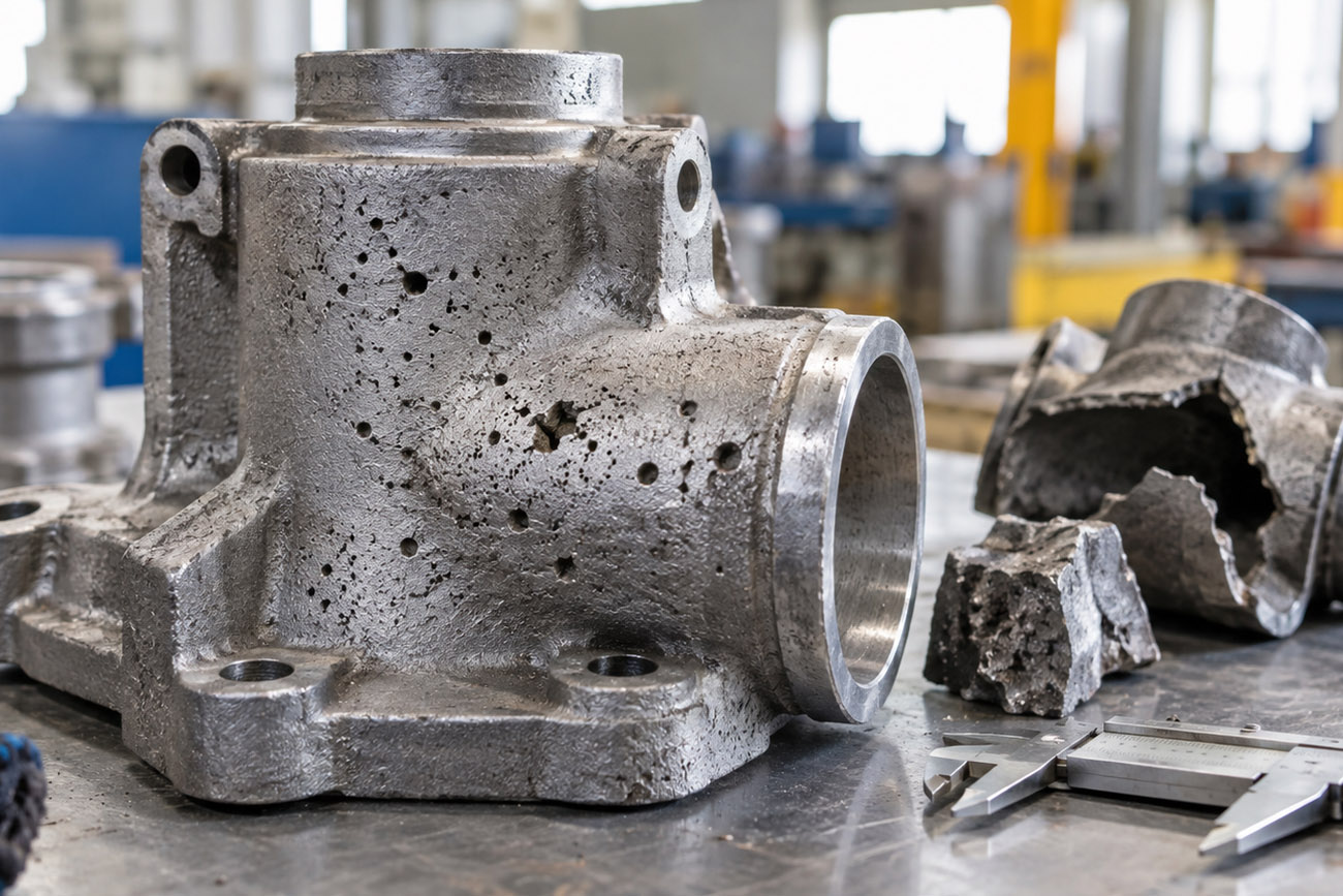
Thick sections cool more slowly and create hot spots. As the surrounding metal solidifies, these areas remain molten longer and can shrink as they cool, leaving shrinkage cavities or interdendritic porosity. Adding a large riser can help feed the area, but it also increases metal loss and grinding time. A more effective approach is to design for uniform section thickness, hollow out bulky bosses with cored holes, and connect regions using ribs instead of heavy junctions. Where thickness changes are unavoidable, generous fillets can smooth the transition and reduce turbulence during filling. Consider a gearbox housing with a 20 mm boss blended into a 6 mm wall. Coring the boss and adding two ribs can shorten solidification time, reduce riser size, and lower scrap without sacrificing stiffness.
Overspecifying Tolerances and Surface Finish
Casting capability varies by process. Sand casting generally produces rougher surfaces and looser dimensional control than investment casting or die casting. Applying tight GD&T requirements to every feature often forces extensive machining, additional machining stock, and extra setups. Place datums on intentional machining pads rather than on cast surfaces near the parting line, where flash or mismatch can occur. Identify dimensions that are critical to function for features such as bores, bearing seats, and gasket lands, while allowing noncritical ribs and exterior contours to remain in their cast condition. Similarly, requiring a fine Ra value across a broad exterior face on a sand casting can increase processing time significantly. Reserve polished finishes for sealing or sliding surfaces and allow suitable cast texture elsewhere to help control cost and lead time.
Poor Core Design and Difficult Cored Passages
Cores need proper core prints to support their weight and resist buoyancy when molten metal surrounds them. Long, thin passages with high length-to-diameter ratios are more vulnerable to breakage, gas-related defects, and core shift, which can move internal holes away from their intended positions. Venting paths must also allow binder gases to escape, while chaplets should generally be used only when necessary rather than serving as the primary design strategy. If an oil gallery is modeled as a 6 mm diameter hole extending 200 mm through a sand cast wall, manufacturing difficulties are likely. Increasing the diameter, dividing the passage into shorter intersecting cores, or designing a straight drilling path with an entry boss can improve yield and reduce internal defects while preserving the required function.
Skipping the Quality Plan: Sampling, Heat Treatment, and Inspection
Dimensional and metallurgical control do not happen automatically. A focused quality plan can define first-article inspection using a CMM, identify leak or pressure testing for sealed housings, and specify any nondestructive evaluation, such as radiography or dye penetrant testing, for thin ribs and fillet junctions. If the alloy requires heat treatment, specify the required temper and hardness targets along with datum schemes that account for distortion during later machining. Consider requesting solidification or fill analysis when riser placement is limited or when previous designs have experienced gas entrapment. Planning how riser pads will be removed and which surfaces will be machined after stress relief can also prevent surprises, such as discovering a porosity pocket beneath a cosmetic face that was intended to remain unmachined.
Building a More Predictable Casting Process
Thoughtful casting geometry can quickly reduce defects and improve lead-time predictability. Add realistic draft to vertical faces, keep walls as uniform as the design allows, and use ribs and cored cavities to reduce hot spots that can contribute to porosity. Apply tight tolerances and fine finishes only where function requires them, and place machining datums on stable pads away from parting lines. When cored features are necessary, support them with adequate core prints and practical length-to-diameter ratios, or consider machining the passage afterward. Finally, establish a clear written quality plan before producing tooling. Early design reviews with your foundry can turn these decisions into a stable manufacturing process rather than a series of costly corrections.